Increased parallel resistor stages will increase overall input Wattage. The Rhombic Antenna is an equilateral parallelogram shaped antenna.
Rhombic Antennas
General Discussion of Directional Antennas.

. Chapter 13 of The ARRL Antenna Book 21st ed includes a discussion of rhombic design and construction considerations Switching. The paper discusses the theoretical methods employed by the authors in dimensioning horizontal rhombic receiving antennas. Above the ground plane the half-rhombic antenna exhibits the radiation patterns of a full-rhombic antenna while the input impedance is half that of a full-rhombic antenna.
V angle at each end. Generally it has two opposite acute angles. A rhombic antenna may also be considered as a combination of 2 V antennas or inverted V antennas forming an obtuse angle.
εr is relative dielectric constant of the material. It is symmetrical around the long side of the antenna. Feb 20 2014 2 Not many people use Rhombic antennas as they take up a lot of room and.
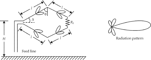
The rhombic is made of 4 wires of length L in a rhomboid shape in the horizontal plane see fig 1. Antenna was simply too high for it to be ef-fective in the opposite bearing. So no waiting for a rotator to turn the system has every direction every band every time.
The Rhombic is an equilateral parallelogram shaped antenna it has two opposite acute angles. H is height of the substrate and W is the width of patch calculated in first step. Design equations of Rhombic antenna From this equation we can deduce the condition to get the maximum power direction with respect to height h and length of line L The main disadvantage of rhombic antenna is that the portions of the radiation which do not.
The maximum gain is 744 dBi. Generally it has two opposite acute angles. While three of the rhombics are two-wire designs the Caribbean rhombic employs three parallel runs of 12 Copperweld wire.
The excitation to the antenna is provided through feed lines. Captain Kilowatt Professional Amateur. Apr 6 2005 16811 10902 823 58 Nova ScotiaCanada.
We havent found any reviews in the usual places. Lets look at a 2 WL per leg 40-meter rhombic design 120 feet high over medium conductivity soil using number 8 AWG bare copper wire with an 800 ohm termination. This is a consequence Feed V S -2R T L L L L D Coaxial Feed R T L L D Ground Plane x z.
Then it is placed over a ground plane. A set of simplified equations is. At first glance our response might be this is a lot of gain.
From inside the book. One peculiarity of the antenna is that its main lobes are quite elevated 45º in this case. To calcualte width W use follwing formula.
It is a combination of two V-antennas. Antenna Theory - Rhombic. Calculate the effective dielectric constant using formula below.
The tilt angle θ is approximately equal to 90 minus the. The tilt angle θ is approximately equal to 90 minus the angle of major lobe. Have any of you guys used one.
After all the gain is a whopping 1442. It is arranged in the form of a rhombus or diamond shape and suspended horizontally above the surface of the earth. Rhombic antenna is cut at the feed and resistor.
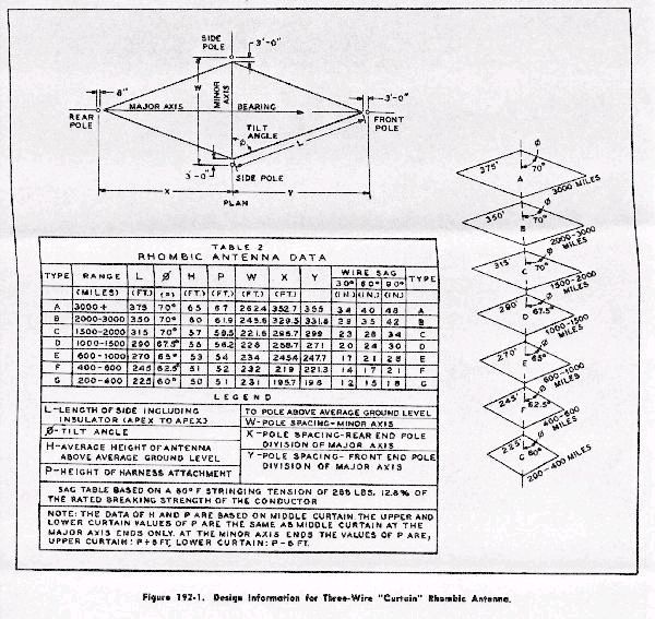
Input W R1ab Ω R2ab Ω R3ab Ω Rab Ω 9dB ERP 10W 400 none none none 80W. A rhombic antenna is made of four sections of wire suspended parallel to the ground in a diamond or rhombus shapeEach of the four sides is the same length about a quarter-wavelength to one wavelength per section converging but not touching at an angle of about 42 at the fed end and at the far end. Good symmetry is of vital importance for the performance of this antenna.
Void has left would-be rhombic designers with no better information than we had in the 1940s. Van Nostrand Company Incorporated 1941 - Radio - 111 pages. Resources listed under Antenna Calculators category belongs to Antennas main collection and get reviewed and rated by amateur radio operators.
Multi-Band Multi-Wire and Multi-Element Rhombics L. This is discussed in the next chapter. This feed line can be two-wire transmission lines or coaxial wire that excites the whole structure.
There are included brief descriptions of the antennatotransmission line coupling circuits and the. Cebik W4RNL SK Because the rhombic antenna especially when terminated offers very high gain it has received more design attention than any of the other long-wire antennas. The Rhombic Antenna is an equilateral parallelogram shaped antenna.
Antenna design calculators category is a curation of 90 web resources on The Magloop Antenna Calculator Parallel Square Conductor Transmission Line Calculator Magnetic Loop Antenna Calculator Spreadsheet. Interesting antenna and he commented that fade was not nearly as bad with this design as it is with others. Rhombic antenna in free space F14 MHz L2142 m and A62º.
The figure below represents the rhombic antenna. What people are saying - Write a review. Calculate ΔL using formula below.
The antenna is bi-directional having two main lobes along the Y-axis and two secondary lobes along the X-axis. In general we treat long-wire. Side length one of four sides.
Long-Wire Antennas Part 5. The potential long-wire antenna builder is left with some fundamental equationsmostly dating to the 1930sand has no guidance as to whether we should assign some limits to them. Experimental proof is given of the engineering accuracy of the directivity calculations on which this work is based.
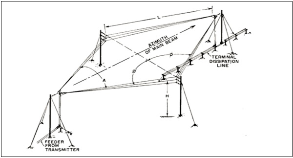
Rhombic termination resistor Termination resistor needs to be near 800Ω Resistors must be carbon resistance - not inductive. The width of the antennas main lobe is determined by the angles q and a often referred to as tilt and apex angle. Equations for solving the deflection and bending moments of rhombic plates by exact method are known to be highly tedious.
Rhombic antenna works under the principle of travelling wave radiator. A rhombic antenna design works best at a height of one-half to a full wavelength at the lowest F. All resistors are carbon 5W creating 10W max dissipation per leg.
After the V-antenna and inverted V-antenna another important long wire antenna is the Rhombic antenna.

Rhombic Antennas For Television October 1949 Radio Television News Rf Cafe

Long Wire Antennas Vee Antenna And Rhombic Antenna Book Sources K D Prasad J D Krauss Ppt Download

Rhombic Antennas For Television October 1949 Radio Television News Rf Cafe
Kb1sg S Amateur Radio Rhombic Pages Rhombic Antenna Design
Rhombic Antenna Features Advantages Electronics Club

Long Wire Antennas Vee Antenna And Rhombic Antenna Book Sources K D Prasad J D Krauss Ppt Download
Antenna Theory Rhombic
Ea4fsi 28t1 Hf Antennas Rhombic Antennas
0 komentar
Posting Komentar